Capacitors are the electronic component designed to store energy, isolate DC signals and transmit AC signals, stabilize voltage. It perform no real task but provide a necessary assist to other task-oriented electrical components. However, the capacitors are prone to failure due to age, heat, or voltage stress. Testing a capacitor is critical for troubleshooting electronics.
Safety First: Discharging Capacitors
Discharge capacitors before testing, to avoid electric shocks or damage to equipment. A charged capacitor can retain dangerous voltage even after being disconnected from a circuit.
Different type of capacitors require different discharge methods.
For high-voltage capacitors, use a resistor with a high wattage rating (e.g., 10k ohms, 5 watts) to discharge slowly. Connect the resistor across the terminals with insulated clips until the voltage drops to near zero.
For low-voltage capacitors (under 50V), short the terminals with an insulated screwdriver.
Then confirm discharge with a multimeter set to DC voltage mode. (Safety gear: wear insulated gloves and safety goggles. Never touch terminal directly.)
Visual Inspection
The simplest method involves checking for physical damage.
Bulging/Leaking: Electrolytic capacitors often bulge at the top or bottom due to gas buildup.
Burn Marks/Cracks: Look for discoloration or ruptured casings, common in ceramic or SMD capacitors.
Lifted Terminals: Common in surface-mount capacitors after thermal stress.
Use a Multimeter With Capacitance Setting
Using a multimeter to assess its health by measuring capacitance. Set the digital multimeter (DMM) to capacitance mode (marked with a “C” symbol).
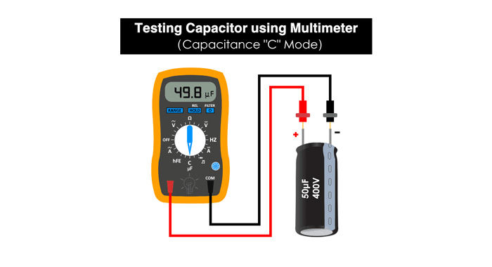
Source from Internet
Steps:
1. Connect probes to terminals, observe the correct polarity if it is polarized capacitor: the red probe to the positive terminal and the black probe to the negative terminal. Holding the probes firmly against the terminals to ensure a stable connection.
2. Compare the reading to the rated value. Typically ±10–20% tolerance indicates a healthy capacitor. If the reading is significantly lower or shows as “OL” (over limit), the capacitor may be open or faulty. While the reading is much higher could indicate a short circuit.
Take a 100μF capacitor as an example. Reading 85μF or 120μF may still be functional. But a reading of 0μF indicates a short or open circuit.
Resistance Mode (Ohm Meter)
Use the resistance mode to check the capability of a capacitor to charge when a current flows through its leads.
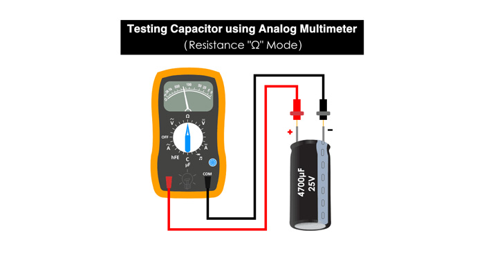
Source from Internet
Set the multimeter to the highest resistance range (e.g., 10kΩ or 1MΩ). Connect the leads of the multimeter probes to the positive and negative terminals of the capacitor to be tested. Current flows through the capacitor, and the capacitor starts charging.
The resistance value start near 0Ω and climb to infinity as it charges, the capacitor works fine. If the displayed value is stuck at very low or 0Ω, it may be a short in the capacitor. On the contrary, it is open if the value is stuck at infinity. Both cases show that the capacitor should be replaced.
Voltage Test
Use a voltmeter to check the charge stored in the capacitor.
1. Charge the capacitor to its rated voltage using a power supply, then disconnect it.
2. Set the voltmeter to the appropriate DC voltage range and connect the probes to the capacitor terminals, observing polarity for electrolytic capacitors.
A healthy capacitor will retain voltage briefly before discharging through the meter. Rapid voltage drop indicates leakage. While no voltage indicates it cannot hold a charge and is likely open or damaged.
This method is useful for troubleshooting power supply circuits and provides a quick indication of the capacitor's ability to hold and release charge.
ESR Meter Testing
Equivalent Series Resistance (ESR) meters detect hidden failures in electrolytic capacitors. High ESR reduces efficiency and causes overheating.
1. Connect the ESR meter probes to the capacitor (in-circuit or removed).
2. Compare the reading to its standard specifications. High ESR values indicate a degraded capacitor.
For example, a 470μF capacitor with ESR >5Ω is likely faulty.
This method allows quick diagnostics without desoldering for working in-circuit.
Time Constant Measurement
The time constant of a circuit is the time taken by the capacitor to charge to 63.2% of the applied voltage through a known resistor, and it is calculated by the formula: Τ=RC
Τ: The time constant of the circuit is commonly referred to with the Greek letter tau
R: Resistance
C: Capacitance value present in the circuit
For example, if a voltage of 10V is applied across the series combination of a resistor and a capacitor, the time constant is the time taken by the capacitance to charge to 63.2% of 10V, which is 6.32V. Use a stopwatch to measure the time taken by the capacitor to charge to this voltage (which is the time constant of the circuit). If the resistor value is 100 ohms, the equation for the time constant can be used to derive the value of the capacitor used in the circuit.
1. Discharge the capacitor completely by connecting it across a resistor, and remove the capacitor thereafter for testing.
2. Connect a known value of resistance in series with the capacitor.
3. Connect the ends of the capacitor to the multimeter probes and set the knob to measure DC voltage.
4. Apply a known voltage (For example, 10V) across the series connection.
5. Measure the time to reach 63.2% of the applied voltage. Using the relation Τ=RC.
Compare the experimental value of the capacitor with that of the printed value on the same capacitor. If both values are nearly the same, the capacitor is in good condition. If there is a noticeable difference between the experimental and printed values, the capacitor is faulty, and it is time to replace the piece.
Continuity Test
A capacitor can be checked for continuity using a digital or analog multimeter.
1. Remove the capacitor to be tested from the electrical board.
2. Discharge the capacitor completely by connecting it across a resistor, and remove the capacitor thereafter for testing.
3. Connect the capacitor leads to the probes of the multimeter (positive terminal to the red and negative terminal to the black probe).
4. Twist the multimeter knob and select the option for continuity check (Select the symbol which shows a propagating wave).
If the meter gives a continuous beep sound (or LED turns ON), there is a SHORT within the capacitor.
If the meter doesn't produce a beep sound, it means that the capacitor is OPEN. If the meter produces a beep sound at first (or turns the LED ON) and gradually stops, it indicates that the capacitor is in good condition.
Caution: Does not assess capacitance or ESR.
Leakage Current Test
Leakage current indicates the amount of current that leaks through the dielectric material of the capacitor. It is crucial for assessing the health of electrolytic capacitors, as it helps identify internal failures and degradation.
High leakage current suggests that the capacitor is failing or has degraded insulation.
1. Discharge the capacitor completely.
2. Connect a DC power supply to the capacitor, ensuring the voltage is at the capacitor's rated voltage, and include a series resistor to limit the current.
3. Measure the current flowing through the capacitor using a multimeter set to the microampere (µA) range.
4. Compare the measured leakage current to the capacitor's specifications. Values exceeding datasheet specs indicate failure.
Dedicated Capacitor Testers
Using a dedicated capacitor tester provides more comprehensive and accurate testing.
Capacitor testers are designed specifically for measuring various parameters of capacitors, including capacitance, ESR, and leakage current. They provide precise readings and are often easier to use than general multimeters.
1. Connect the capacitor tester probes to the capacitor terminals.
2. Select the appropriate test mode on the device (capacitance, ESR, leakage current, etc.), and follow the device's instructions to start the test.
3. Read the results displayed on the tester and compare them to the capacitor's rated values to assess its condition.
Capacitor testers streamline the testing process and provide reliable, detailed information about the capacitor's health, making them invaluable tools for both professional and hobbyist electronics work.
FAQs
Q: Can I test capacitors without removing them from the circuit?
A: Yes, using an ESR meter or CapaCheck 911 device. However, parallel components may affect readings.
Q: Why does my capacitor test good but still fail in-circuit?
A: Hidden issues like high ESR or intermittent shorts may not show up in basic tests. Use an ESR meter for accurate diagnostics.
Q: What's the safest way to discharge large capacitors?
A: Use a high-wattage resistor (e.g., 10kΩ, 5W) to avoid sparks
Conclusion
Testing capacitors requires a mix of methods depending on the application. For hobbyists, visual inspection and multimeter tests are sufficient. Professionals should invest in an ESR meter for in-circuit diagnostics. Always prioritize safety by discharging capacitors and using protective gear. By mastering these techniques, you'll extend the lifespan of electronics and reduce costly downtime.
Pro Tip: For critical systems, replace capacitors preemptively after 5–10 years, as electrolytic types degrade over time